Sunday, January 20, 2019

Marrying a body . . .

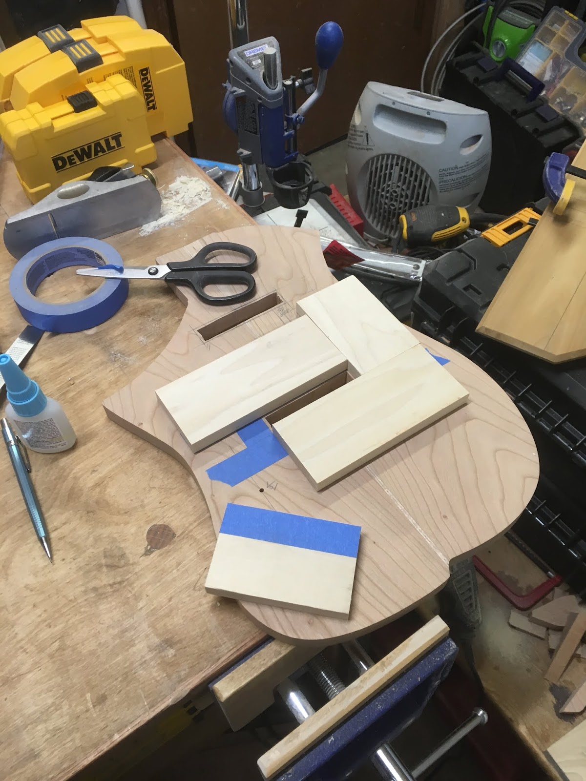
So first I needed to finish cutting the cavity for the controls in the back. The procedure was basically the same as before although I free handed the curve along the outer edge of the guitar . . . thought that making a template was too much work and with a sharp bit and careful thin passes that turned out to be true . . . it wasn't completely smooth but some sandpaper takes care of that . . . and it's the inside.


 Next, well the cable run from the rear pickup to the control cavity (painted with shielding paint here . . . and the hole for the bridge ground . . . Done, ready for the ceremony.

And it pratically impossible to have enough clamps. The boards put pressure on the middle of the glue up . . . important to keep everything flat . . . 


So while waiting for the glue to dry I tackled another project that had been kicking around for quite some time. My JM has staggered Gotoh HAMP tuners . . . advertising says that they don't need string trees . . . advertising may be right in some cases but that group doesn't include mine. Since I got them installed they look good & function well . . . BUT . . . the D string has been twanging behind the nut pretty much since I got the nut set up. Now I COULD just take a couple of winds around the post tho bring the break angle up but that kinda defeats the purpose of locking tuners. Thus back to string trees, the 'problem' is that the hardware is Cosmo Black (aka black chrome) ... try finding some roller string trees in that (hint Gotoh doesn't make any, and what they do make does not roll, though it's OK probably. Finally find some chinese ones that looked likely on ebay . . . and once they arrived they have been kicking around in my box for ....


So her they are ... AFTER ... some judicious use of a file on the left example . . . if I want to stagger them and have the same break angle on all 4 strings and have the stings exit parallel to the headstock to the tuners some modifications were needed.

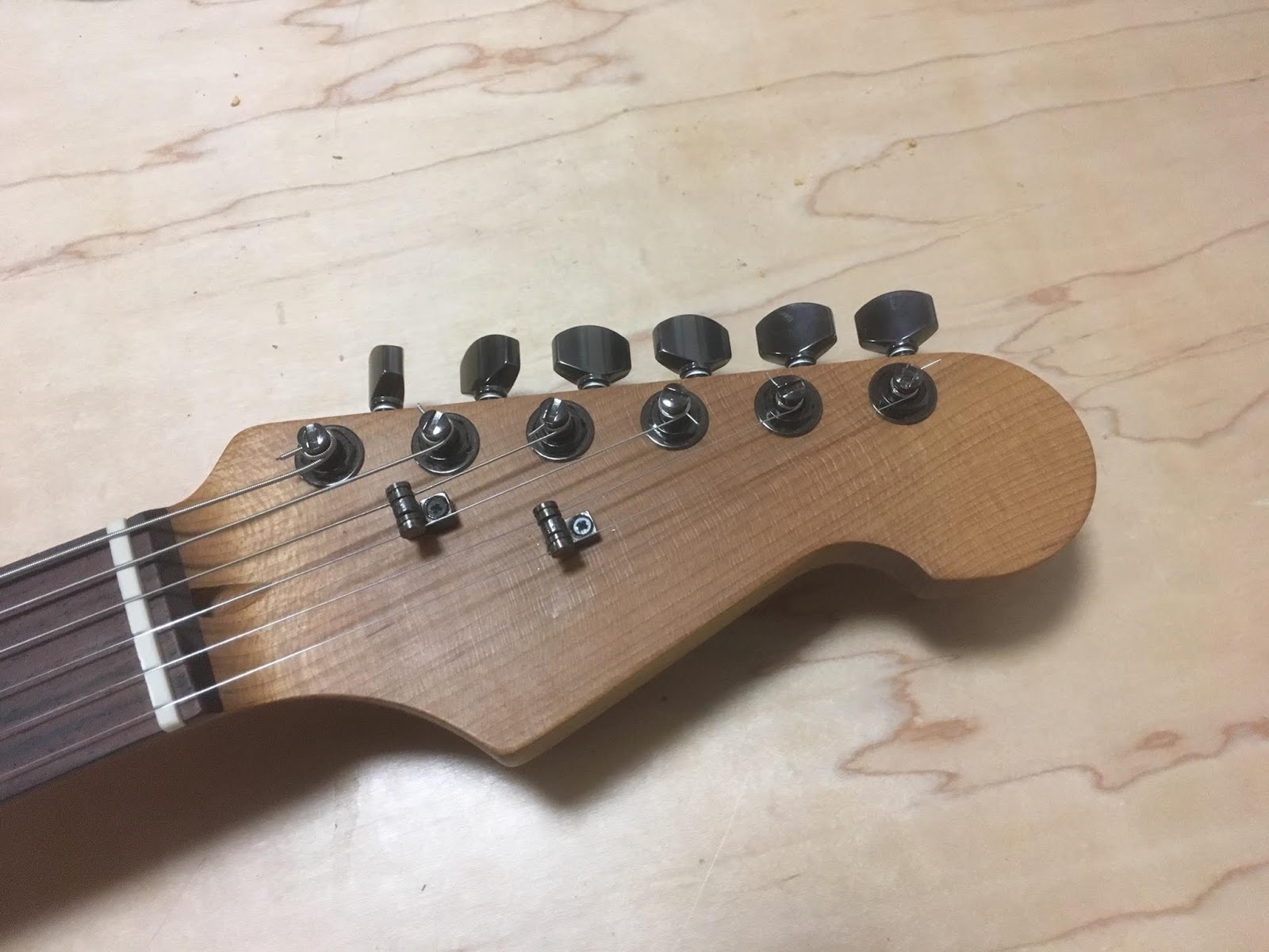
And here they are installed, looks good (even if the screws are still flat black (and half a size to small). More important, the twang seems to be GONE.


After that it was time for operation drip control . . . the starting situation on the left . . . and mostly cleaned up on the right. For the eagle eyed, the glue up was indeed not perfect there is a slight glue line indicating that I need to do a better job flattening the parts before putting them together , , , I may but a 1/8 (or 1/16) wood binding there to hide the boo boo if everything else works out fine . . . I 'll just need to do a better job next time . . . 

Monday, January 7, 2019

And some more holes . . . .


So here the middle of the bridge pickup cutout in the top has been hogged out with a jigsaw (drilled 3/8" hole in the middle and cut about 1/16" inside the edge lines), the blue tape is on the edge lines. Next 1/2" poplar boards were glued around the edge using super glue and the painters tape trick (search YouTube if you don't know that one yet) and finally a 1/2" pattern bit with a top bearing was used to refine the edge . . . easy. Not quite as fast as with a dedicated pattern and not suitable for complex shapes but for the occasional rectangular cutout it works perfectly.


And both pickup holes are done . . . next the cavity for the controls, I either have to cut it now (and have to route to EXACTLY the edge after front and back are glued up OR have to cut in from the edge later . . . not even sure if that would be possible as you would need a really long motising bit OR a really large groove cutting bit and even then quite a bit of chiseling would be required through a small opening with a 1/16" thick piece of wood on one side . . . I don't have either of those bits (if the first even exists) and I'm not that good with chisel so I'll cut it now . . . 


You can see the channel for the wires cut with a bowl bit in the first photo - and some cutting were the controls will go . . . got stupid again and tried to ease the bit in with a fixed base . . . no, no , NO of course the bit grabbed and, no permanent damage to either the work piece or my fingers but I SHOULD have know better and not even tried . . . dumb, dumb, DUMB. So I assembled the router in the plunge base, as I should have done in the first place, and cut the channel. The outside edge for the cavity MUST be in EXACTLY the right place otherwise the cavity will not be deep enough OR it won't be open on side to accept the controls thus measure, measure, check & measure again so you KNOW it's right . . . here the tape (and 'template') is actually 2 mm OUTSIDE the lines to be cut as I'm using a pattern insert with a 1/4" spiral bit . . . a bit of an experiment as I came across these bits at Harbor Freight, 3 for ... $9? I think ... only HSS not carbide but . . . we'll see . . . and measure, check, check and measure for final depth. It won't do to go through the top after all this work . . . I tried to take light passes but . . . there's always a but . . . lets leave it at that, it didn't go as expected but in the end no permanent damage was done beyond uttering some words that shouldn't be repeated in polite company. No fault of the bit though, I wouldn't want to use it for heavy work, one deeper pass had a LOT of burn but go easy and it does the job . . . 

Oh and I need to check that template guide, the bit was off by about 0.3-0.5 mm not sure if it's the template guide [also from Harbour Freight - but it seems correct], the template base [from MLCS - unlikely to be wrong] OR the plunge assembly [factory set up from Makita, the likely offender at this point] EVERYTHING fits tightly together yet, one side is further from center than the other; it doen't matter much here as long as I KNOW about it but for accurate work this needs to be corrected.


Final depth confirmed with the depth gage to be 15.76 mm I was shooting for 15.50 . . . the wood is 18 mm thick and I wanted a minimum of 2 mm (~ 3/32") over the top and a 13-14 mm opening (a lever switch requires about 13 mm to put in while regular miniswitches are between 10 and 12.5 mm) so I got what I wanted. Painted both top and bottom with shielding paint (something else that would be a chore once things are assembled . . .  and the cavity for volume & tone pots has also been started . .

Now to decide what else to cut out from bottom and top to make it as light as possible . . . and then we can marry them . . .