Showing posts with label electronics. Show all posts

Monday, April 9, 2018

(Micro) surgery on a headphone plug

So my favorite pair of earphones used to be a Klipsch S2 . . . until the plug developed an intermittent  problem which was probably a partial break in the ground wire. I've had this sitting around for a while now WITH a new plug for replacement but just haven't ever gotten to it ... till now.


So fortunately the wires seem to be color coded so we can just cut the thing, figure out what's what at the plug end and then resolder the wires into the new plug . . . . the copper is PROBABLY the common ground with the red either the right or left ...


Wires ready to solder into the new plug, yes the copper DID turn out to be the common ground . . . 


First one done . . . 


All soldered up . . . I was smart and remembered to check diameters before starting soldering, so there are 4 layers of heat shrink tubing around the wire to fill the hole on the plug and for strain relief . . . 


All done, I really enjoy these much more than the 'cheap' pairs I have been using . . . MUCH flatter response than almost all bass heavy cheap pairs I've been trying/using for a while now (some of them are really unusable for anything for bass heavy modern stuff . . . and that's just NOT my thing) . . . . unfortunately the pug is to big to fit through the opening in my phone case but I'll take that for the better listening experience. 


Monday, March 26, 2018

And it's back together . . . .

Well . . . it's back together.

Body cavity lined with copper (in progress) . . . check


Wiring complete . . . check


Tune up, let it rest a bit and redo the action & intonation . . . working on it . . . 


Ok it was a little more complicated than that . . . 
. . . there was a faulty switch in the neck PU coil selection unit that took me a while to run down, though I learned a new trick soldering switches . . . or maybe relearned an old one. 
. . . the original placement of the treble bleed prevented the guard from falling into the right place . . . and then when bent to a more 'convenient position' shorted out against the copper lining.
. . . when testing the resistance readings got really weird . . . due to a inversely wired tone pot . . . and then the volume pot behaved weird (see below).
. . . and then there is the switch in the tone circuit that behaves . . . not like it should . . . despite testing OK . . . 3 times . . . there seems to be some kind of 'non continuity' there that prevents the tone pot from correctly shunting signal to ground via the cap . . . which may be a wiring fault . . . 

The coil selection (where I though I had a wiring fault) now works flawlessly; GOOD. The treble bypass is quite subtle but noticeable. However, my trim pot went missing so I'll have to redo that part once a replacement comes in; OK. And then there is the tone knob . . . I think I have another faulty switch there - despite the fact that it seemed to check correctly - as there is something weird going on, I get (almost?) no tone rolloff when I have it in the prevolume position, while it - occasionally - DOES work when in the postvolume position . . . SO . . . that's another thing to check out . . . . . 

OH and this IS the LAST time I do anything this COMPLICATED . . . . . . . . . . . . the rewire took two solid days of work to complete . . . . . . 

. . . and there is something WEIRD on the volume pot; if you measure resistance between the IN & OUT lugs of the volume pot when wired up the resistance goes from 0 to 480K (or so) when turning the wiper and then on the last 5% of the range or so DROPS almost instantly to almost 0 on one of my multimeters . . . . the pot itself is fine . . . I unwired and rewired it twice thinking I had damaged it in soldering the leads . . . it behaves as it should but there is something WEIRD going on in the circuit . . . I'll have to see if I can run down next time I get the guard off.


Tuesday, March 20, 2018

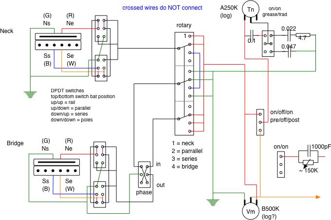
Stupid mistakes . . . and a redo of the wiring diagram ... again

AND . . . one more time


OK so I managed to do a number on myself with the last revision of the coil selection switches . . . it was WRONG (mea maxima culpa) so that's been corrected - thanks to another question about humbuckers and series switching, I should trust myself a little more . . . SD humbuckers connect red to white for series . . . and that just wasn't happening before. The tone stack has also been revised. The 'grease bucket' (tm)  circuit has been removed as I couldn't figure out how to build it and a regular tone circuit on the switch ... I'll try that one again when I have some more time . . . AND . . . I wanted to try a treble bleed from the beginning so that's in there now with an on/off switch so I can see what and how much it does.

Making progress . . . . .
. . . . so far all the checks seem to come back as they should.

Left to do, build the treble bypass, finish the tone switch & knob . . . . . and wire it all to the jack. And ... transfer the harness to the actual pickguard and wire in the pickups . . . .


Oh and it turns out that guitar making IS a transferrable skill.

Tuesday, March 13, 2018

And ... another rewire . . . .

OK, after a while the neck pickup in the JM developed an annoying ... seemingly unreproducible problem . . . scratchiness . . . anyway it was painfull to listen to SO back to the diagram and trying to find WHERE I went wrong . . .

Well no faults leading to scratchiness were found . . . BUT . . . it look like the humbucker coils were wired out of phase . . . OUCH . . . start and end somehow got interchanged on the P90 part of the pRails.

EDIT / UPDATE: NO, no, NO . . . they were NOT . . . it's now been corrected in the next post

OK so here is the new diagram . . . and apologies to anyone who tried it . . .


So I took the whole instrument apart and . . . well in the end I think that an non insulated ground wire in the pickup coil switching circuit occasionally could make contact with the hot signal from the neck pickup depending on the vibration and other factors . . . not solid contact mind you, but just kinda glancing off of it ... thus the scratchyness . . . ??? . . . that's the only thing I could find remotely problematic electrically . . . and of course . . . it's hard to see through a solid wood body or pickguard and things undoubtedly move on installation and . . . . 

Also took the opportunity to rout out some 'tight spots' where the pickup legs were a 'tight' fit and to rout a shorter path from the bridge pickup to the coil switching circuit in the upper horn . . . and debating whether I want to coat the whole interior with copper shielding foil while I have it apart . . . 

Anyway here are some shots of work in progress:

First shot is the coil switching circuit being built. The second has the coil switching circuit and the phase switch complete and the rotary pickup selector switch is being built. No cloth wire this time, it's not bad to work with but I didn't have enough for a complete rebuild and it's more bulky than the silicone insulated hookup wire.


Volume & tone next week, I have to have a look at the tone circuit before I put that in (EDIT: done that and yes there was a mistake that has been corrected), the SPDT on/off/on switch should switch the tone circuit before or after the volume pot . . . just to try if it make a difference (quite possibly not), the other switch should give me a straight cap like a normal tone circuit OR a version of the Fender grease bucket circuit . . . 

Thursday, February 22, 2018

One more circuit . . . .

Switching 3 PU off/series/parallel the switch positions would be better labeled off/out/send as the last setting sends the signal to the next PU in the chain and the middle position sends it out of the chain.


And here is the 2 PU version . . . .


Thursday, April 6, 2017

2 and 3 way switches for single coil switching


A question led to drawing out the schematic for switching 2 single coils with a 2 & 3 way slide switch . . . here it is.


Monday, February 27, 2017

All's good . . . . . .

Well the electronics are still subject to revision but here she is . . .

The pick guard contains an (unintentional) Esher like joke though. Better pictures once the weather lets up here.

Changing out the pick guard was relatively easy once I figured how the screw holes lined up . . . the only 'problem' was 2 solder joints on the rotary switch 'broke' . . . bad soldering on my part I guess. I first thought I had a ground fault on the bridge PU as it barely made any sound . . . turns out the ground lead AND the hot lead came off the switch. The ground was an easy fix but I initially soldered the hot to the WRONG PIN . . . and was wondering why it was so clean (no solder on it what so ever) when I did it . . . it was only after the PU still failed the tap test that I figured that one out . . . .

Saturday, March 12, 2016

DigiKey

A package arrived yesterday with a lot of bits & pieces  for the electronics of the guitar ... and I was impressed. I have ordered stuff from Mouser before and it was fine, this however was more than just fine. It arrived within 3 days with all the components seperately packaged in clearly labled ziplock bags ... nicely done guys. So now I have everything I thought I needed ... undoubtedly I'll find something I have forgotten ... maybe need more pushback wire ... and have to get off my ... ... ... behind ... ... ... and cut that first version of the pickguard ... ... ...   ... ... ...   ... ... ... after swimming my laps ... ... ...

OK so an update ... unpacked all the bits and pieces and ... checked that I now have everything ...
Yep it all SEEMS to be here now .....

Bit of a scare though ... the volume pot was marked D not A ... some Googling (yep that is apparently now officially a verb WITH a Capital letter ... even autocorrect recognizes it) shows that this is the way Bourns (and that is NOT in autocorrect) codes audio taper pots ...

Now if it will only fit the way I think it should ...
And yes ... it does seem to fit ... going to be tight down there as there are two SPDT on/off/on switches between those two tone pots on the bottom but it'll fit ... I think and there is plenty of space below the pickups for the tone caps ... the test configuration has 4 rather large axial orange drops .........

Oh and I though that I had lost the baggy with the screws for the jackplate ... pffffff ... they were loose in the bottom of the parts box so I decided to install it before they disappeared.
Looks pretty classy if I do say so myself.

UPDATE: saw the photo again today and ... well the 'silverish' rectangle at the top is just a reflection ... fortunately. The line on the right is a (rather less noticeable in real life) scratch though.